Determine what the valve is supposed to do
- Is this valve used for tight control or is”loose”control acceptable. (For instance, are you trying to control a flow within a very tight margin across a broad range of process conditions or are you simply throttling a charge flow down as it approaches setpoint to avoid overshoot). The requirements for one situation are quite different from the other.
- Is this valve supposed to provide control or tight shutoff? A valve can almost never do both. If you need both, then add a separate on/off shutoff valve.
Understand the TRUE process conditions
- What is the minimum flow that the valve must control?
- What is the maximum flow that the valve must pass?
- What are the TRUE upstream/downstream pressures and differential pressure across the valves in those conditions? (Note that the P1 and DP at low flow rates will usually be much higher than at full flow rates. If you see a valve spec showing the same DP valve for high and low flow conditions it will be wrong 95%+ of the time).
- What is the min/max temperature the valve might see? Don’t forget about clean out/steam out conditions or abnormal conditions that might subject a valve to high steam temperatures.
- What is the process fluid? Is it always the same or could it be a mix of products?
Note that gathering this data is probably the hardest to do.It often takes a sketch of the piping, an understanding of the process hydraulics, and examination of the system pump curves to determine the real pressure drops under various conditions. Note too that the DP may change when you select a valve since it might require pipe reducers/expanders to be installed in a pipe that is sized larger.
Understand the installed flow characteristic of the valve
This can be another difficult task. Ideally the control valve response should be linear (from the control system’s perspective). If the PID(Piping and Instruments Diagram)output changes 5%, the process should respond in a similar fashion regardless of where the output is. (In other words 15%~20% or 85%~90% should ideally generate the same process response.) If the valve response is non-linear, control becomes much more difficult. (You can tune for one process condition but if conditions change the dynamics change and now the tuning doesn’t work nearly as well.)
The valve response is determined by a number of items including:
- The characteristics of the valve itself. (It might be linear, equal percentage, quick opening, or something else.)
- The DP of the process – The differential pressure across the valve is typically a function of the flow (the higher the flow, the lower the DP across the valve). This will generate a non-linear function.
- System pressure and pump curves – pumps often have non-linear characteristics as well, so the available pressure will vary with the flow.
The user has to understand all of these conditions so you can pick the right valve plug. Ideally you pick a valve characteristic that will offset the non-linear effects of the process and make the overall response of the system linear.
If the pressure drop is high, you may have a cavitation, flashing, or choked flow situation
That complicates matter still further because now you’ll need to know a lot more about the process fluid itself. If you are faced with cavitation or flashing you may need to know the vapor pressure and critical pressure of the fluid. This information may be readily available or not if the fluid is a mix of products. Choked flow conditions are usually accompanied with noise problems and will also require additional fluid data to perform the calculations. Realize too that the selection of the valve internals will have a big impact on the flow rates, response, etc. (You’ll be looking at anti-cav trim, diffusers, etc.)
Armed with all of that information (and it is a lot of information) you can finally start sizing/selecting the valve
Usually the vendor’s program is a good place to start, but some programs are much better than others because some have more process data ‘built in’ and have the advanced calculations required to handle cavitation, flashing, choked flow, and noise calculations. Others are very simplistic and may not handle the more advanced conditions. Theoretically you could use any vendor’s program to do any valve but obviously the vendor program will typically have only its valve data built in so if you use a different program you’ll have to enter that data (if you can find it!) One caution about this – some vendors have different valve constants which can be difficult to convert.
The procedure for finally choosing the valve (roughly)
Run a down and dirty calculate to just see what you have. What is the required Cv at min and max flows? Do I have cavitation/flashing/choking issues?
- Run a down and dirty calculate to just see what you have. What is the required Cv at min and max flows? Do I have cavitation/flashing/choking issues?
- If there is cavitation/flashing/choking then things get a lot more complicated so I’ll save that for another lesson.
- Assuming no cavitation/flashing/choking then you can take the result and start to select a particular valve. The selection process includes:
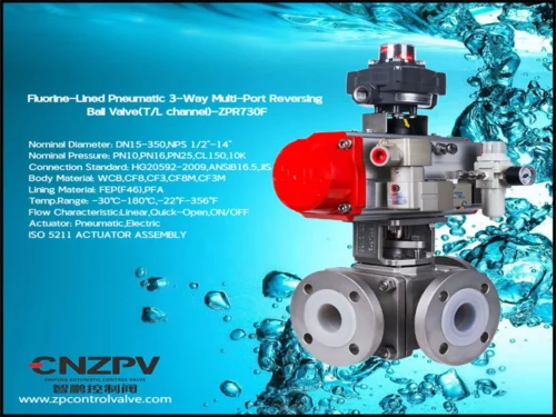
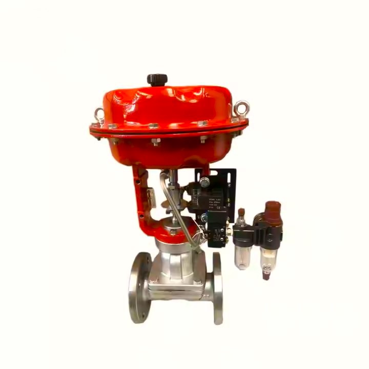
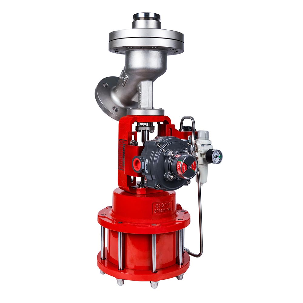
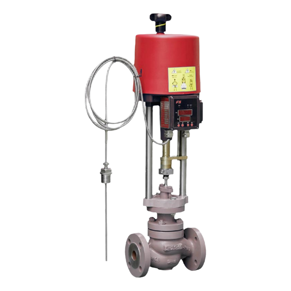
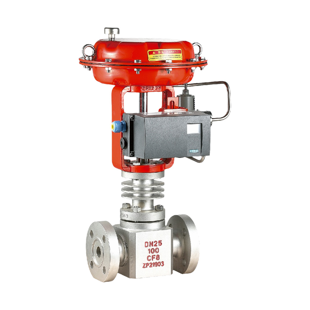
- Pick an acceptable valve body type. (Reciprocating control valves with a digital positioner and a good guide design will provide the tightest control. However other body styles might be acceptable depending on the requirements and budget.)
- Pick the right valve characteristic to provide an overall linear response.
- Now look at the offering of that valve and trim style and pick a valve with the proper range of CVs. Usually you want some room above the max flow and you want to make sure you are able to control at the minimum flow and not be bumping off the seat. Note that you may have to go to a different valve body (or even manufacturer) to meet your desired characteristic and Cv.
- Make sure the valve body/seals are compatible with your process fluid and the temperature.
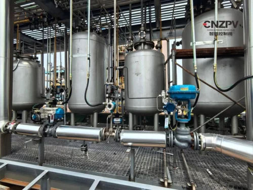
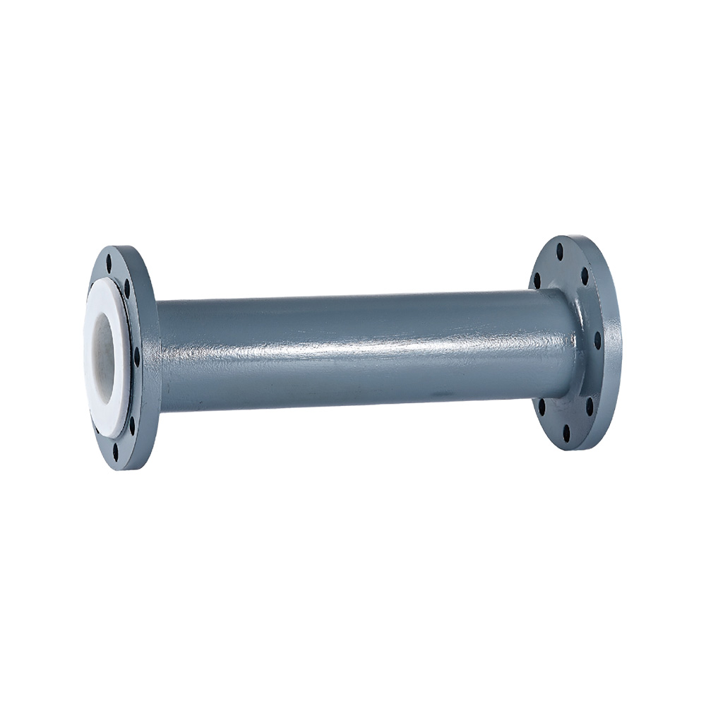
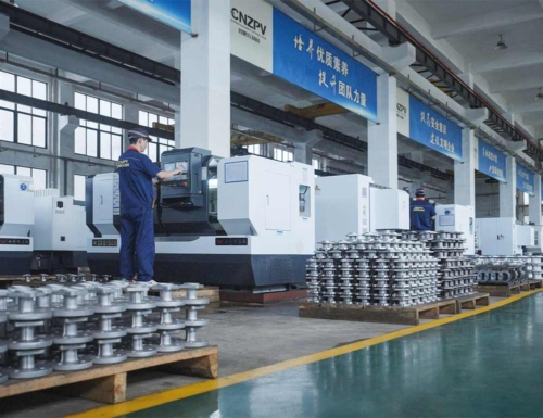
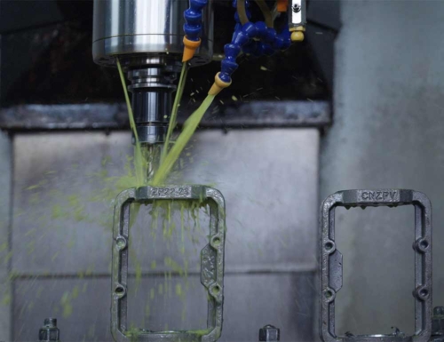
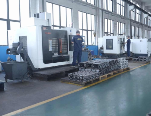
Selecting and sizing a control valve is a complex process. CNZPV is a professional control valve manufacturer. First, determine the valve’s function, like whether it’s for tight or loose control and if it’s for control or shutoff. Then, understand the true process conditions, including minimum and maximum flow, upstream/downstream pressures, temperature, and process fluid. Also, understand the installed flow characteristic of the valve as it’s affected by valve characteristics, process differential pressure, and system pressure. Cavitation, flashing, or choked flow situations add more complexity and require more fluid data. Armed with all the information, start sizing/selecting the valve, usually with the vendor’s program. The selection process involves running initial calculations, picking an acceptable valve body type, the right valve characteristic for linear response, and a valve with the proper CV range. Ensure the valve body/seals are compatible with the process fluid and temperature. If you have any questions regarding control valves, contact us and our experienced experts will help you solve all problems.