Meta Description: Ensure proper control valve operation with our step-by-step FAT guide covering ANSI/ISA 75.25, ISO 5208, and API 6D compliant testing procedures for valve positioning & pneumatic actuator alignment.
Control Valve Pre-Shipment Verification: Critical Checks
Proper validation of valve trim position and actuator direction is mandatory per IEC 60534-8 to prevent field failures. Below are certified inspection protocols:
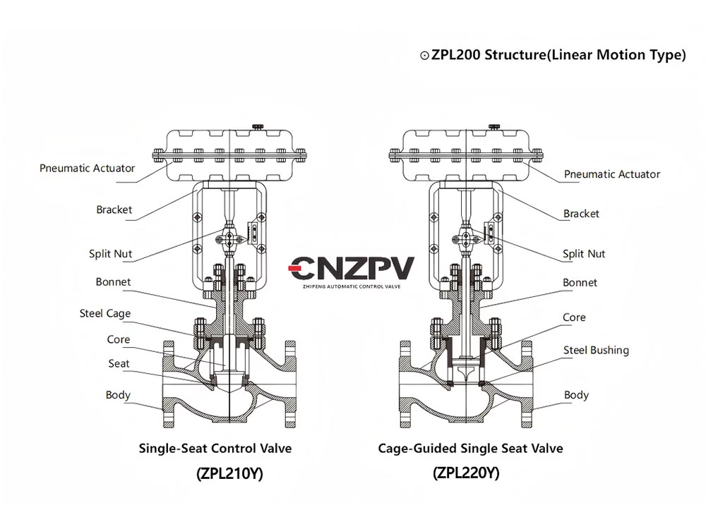
1. Valve Trim Position Verification
1.1 Manual Operation Test
Complies with ISO 5208 Class IV leakage standards
Tools:
Handwheel (for gearbox actuators)
Manual override (pneumatic actuators)
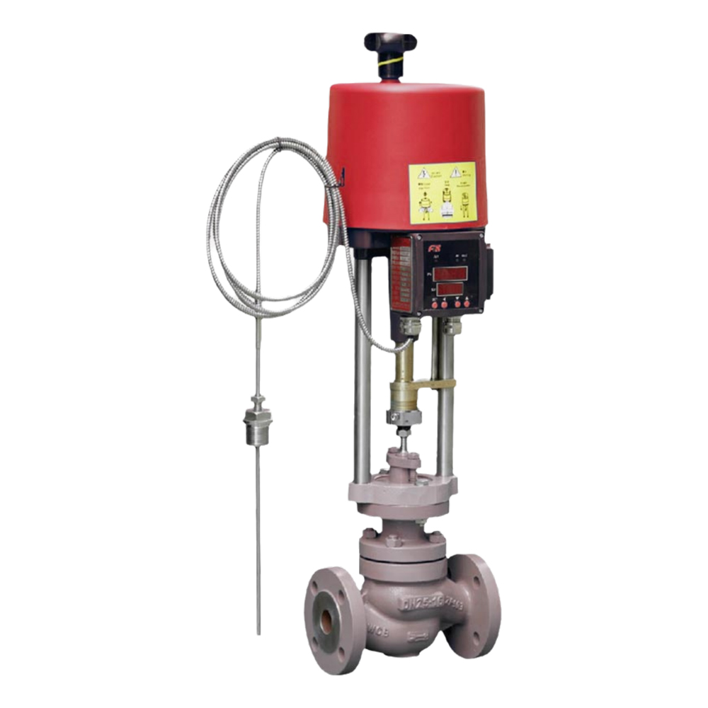
Torque wrench (electric actuators)
Procedure:
Closed Position (0%):
Verify stem reaches mechanical stop
Perform bubble-tight test using 0.6 MPa air (ANSI/FCI 70-2)
Open Position (100%):
Confirm full travel per ISA 75.11 stroke specs
Check flow path obstruction via compressed air purge
1.2 Stroke Calibration
Meets IEC 60534-3 linearity requirements
Equipment:
Dial indicator (accuracy ±0.1mm)
HART communicator (for smart positioners)
Tolerance:
Linear valves: ±1% of rated travel (e.g., 25mm → ±0.25mm)
Rotary valves: ±1° for 90° travel
1.3 Limit Switch Adjustment
Certified to EN 60947-5-1
Mechanical switches:
Set NO/NC contacts to trigger at 95-100% travel
Proximity sensors:
Adjust sensing gap per manufacturer’s datasheet (typically 2mm)
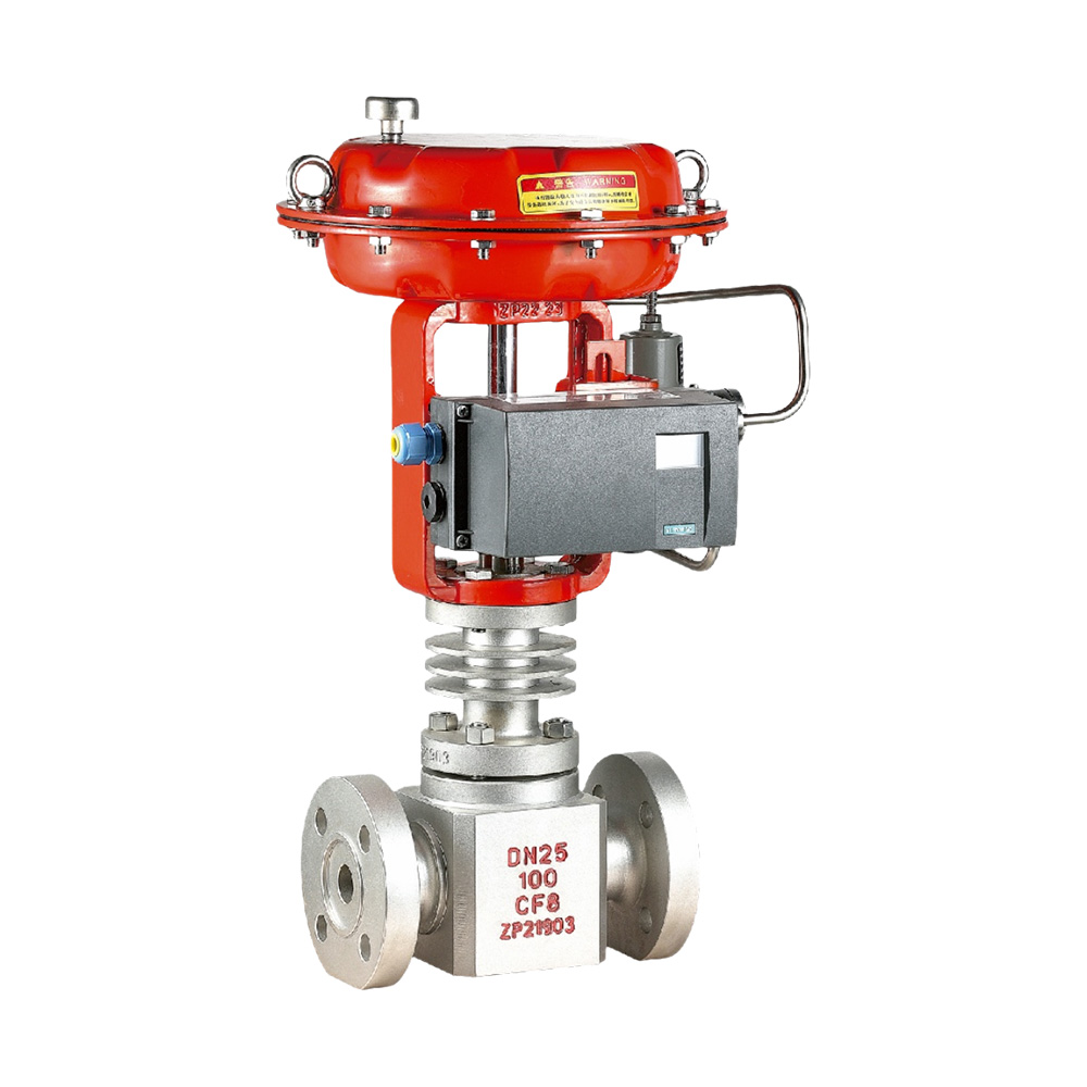
2. Pneumatic Actuator Direction Validation
2.1 Action Types (Per API 6D Annex F)
| Type | Signal Action | Fail-Safe Mode | Application |
| Air-to-Open (ATO) | Air ↑ → Valve opens | Fail-Closed (FC) | Cooling water systems |
| Air-to-Close (ATC) | Air ↑ → Valve closes | Fail-Open (FO) | Fuel gas emergency lines |
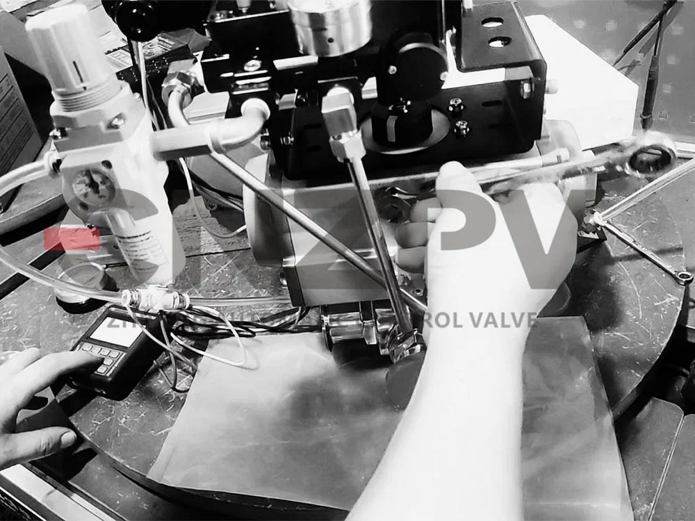
2.2 Direction Test Protocol
Follows ISO 5211 mounting standards
Supply 0.5 MPa air via FRL unit (Filter-Regulator-Lubricator)
Observe stem movement:
Extending stem = ATO action
Retracting stem = ATC action
For reverse action: Swap Port A ↔ Port B connections
2.3 Troubleshooting Guide
| Issue | Root Cause | Corrective Action |
| Travel ≠ 4-20mA signal | Improper span calibration | Recalibrate using HART 375/475 communicator |
| Wrong fail-safe position | Incorrect spring assembly | Reconfigure per EN 15714-3 guidelines |
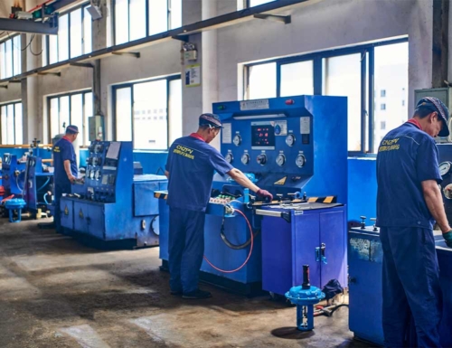
3. FAT Checklist (API 6D Appendix A)
Mechanical inspection: Smooth operation with ≤2 Nm friction torque
Seat leakage test: Max 50 bubbles/min (ANSI Class IV)
Stroke verification: 3 full cycles at 20%/50%/100% signals
Direction confirmation: P&ID vs. actual movement cross-check
4. Key Compliance Notes
Explosive atmospheres: ATEX Directive 2014/34/EU Category 2G/3G
Materials: NACE MR0175 for H₂S service
Documentation: Include test certificates per ISO 10474 3.1B